Sponsored

Restraints Indicator Lamp Warning, Radio and Climate Physical Buttons (FCIM) not working, No Outside Temperature, No Start/Stop Either

RangerBill

Well-Known Member
First Name
Bob
Joined
Jun 8, 2022
Threads
3
Messages
1,661
Reaction score
2,224
Location
PA
Vehicle(s)
2019 Ford Ranger Lariat Super Crew FX4
Occupation
retired
I appreciate it, could there have been something with the Engine Compartment wire harness being replaced?
Without knowing what harness was replaced, it is hard to tell.
Sponsored


RangerLife

Member
First Name
Anthony
Joined
Jan 8, 2024
Threads
0
Messages
22
Reaction score
8
Location
USA
Vehicle(s)
2020 Ford Ranger

airline tech

Well-Known Member
Joined
Aug 24, 2022
Threads
28
Messages
4,499
Reaction score
8,592
Location
Midwest - KS
Vehicle(s)
2022 Ranger Lariat-Super Crew, Cactus Gray
Occupation
Aircraft Tech
The only way to tell if the replaced wire harness has anything to do with your issue is to perform the wiring checks to the FCIM - Power and Ground and the Can Bus circuit integrity.

Without those checks you are shooting darts in the dark.
Here is a related video - not Ranger specific but a good video reference of what I am pushing to be checked.
He is performing the checks you need to pinpoint it down to FCIM or Wiring issue, however he is not checking for power and ground in the video - as the whole bus is dead, your issue is only partial loss.
So check for Power & Ground and use the previous posts and the below video as a guide to check the Can-Bus circuit. If Can Bus wiring - I highly suspect the issue is between the TRM & FCIM.
These simple checks will provide some valuable information and give some direction on where to go next.
I still strongly feel the FCIM is not receiving the (ISP-R) data signal, but we need to actually confirm that the FCIM is receiving power and has a good ground.

2018 Ford F-350 6.7L Medium Speed CAN Bus Issues (No HVAC Controls)


airline tech

Well-Known Member
Joined
Aug 24, 2022
Threads
28
Messages
4,499
Reaction score
8,592
Location
Midwest - KS
Vehicle(s)
2022 Ranger Lariat-Super Crew, Cactus Gray
Occupation
Aircraft Tech
I think it may be a good idea since -Some programming has been done to the BCM and that is to check the BCM (As-Built) data lines for (Vehicle Configuration)
Its a shot in the dark here, but since the FCIM is not receiving (ISP-R) data to power up (It Appears)
then we need to back up to the module that will send that information and that is the BCM.
In the As-Built data there are lines of programming that tell the BCM what is installed on the truck.

First lets look at this:

Note:
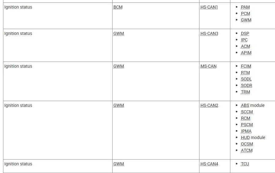
This is showing the (Originating Module) and where the data message is sent via (Can)
So the BCM sends the data via (HS-Can 1) to the GWM, The GWM then sends the data out to the FCIM via (MS-Can)

So in the BCM (As-Built) data lets play (What If?)
What if the BCM is programmed to show that the FCIM is not installed? If so then the FCIM would not receive a (Ignition Status) message

Ign Status.webp


So, lets look at the following BCM (Lines)

726-44-01:
0101-0001-0176
0101-0000-0175 (XL)
Now the (XL) xxxx-xxx0-xxxx) is stated as (ALM Cond Pwr circuit configuration) but should not affect the issue you have and when swapping in a FCIM is not changed.
But however the important (config's are)

726-44-01:
ACM Avail Configure:
xxx1-xxxx-xxxx (0=Absent - 1=Present)

726-44-01:
APIM Avail Configure
xxxx-xxxx-x1xx (0=Absent - 1=Present)

So the above tells the BCM that the modules are present and installed (1=Present)

Now for the FCIM:
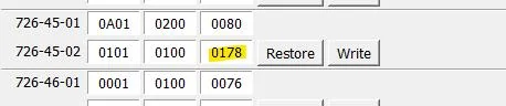
726-45-02
0101-0100-0078
FCIM Available Configure
xxx1-xxxx-xxxx (0=Absent - 1=Present)
If this is set to (o) this is your issue and the Ignition Status message will not be sent out to the FCIM to let it power up.

Plus, since the TRM is showing (not updating or configured) lets look at that setting as well

726-49-01
0001-0001-0079
TRM Available Configure
xxxx-xxx1-xxxx (0=Absent - 1=Present)

So if these settings can be confirmed in the BCM then the BCM should be sending the (Ignition Status) Output message to the modules and it just needs T-Shot down to why they are not receiving the data message.
 

RangerLife

Member
First Name
Anthony
Joined
Jan 8, 2024
Threads
0
Messages
22
Reaction score
8
Location
USA
Vehicle(s)
2020 Ford Ranger
@airline tech Good morning,

When looking at the BCM As-Built file FCIM Configuration shows differently, it shows present, but the last set of digits show "0178" should I try changing it to "0078"?
1748267172350-iu.jpg

My BCM 726-44-01 (Vehicle is XL stock, but since the display is not stock, should it be changed to the "0176"?
1748267299593-se.jpg

TRM:
1748267498418-s9.jpg


Another thing I did notice is they apparently switched out both headlights, the Driver front one was OEM and the Passenger Left was a reconditioned one (unsure why the switched out the left one since there was no damage to that side of the vehicle), and they also apparently switched out the Fog Light Wire Harness as well. When I unplugged the passenger front headlight and started the car, for a quick second the outside temperature showed as "-40" and then went back to showing "--". The fog light harness was also not secured to the placement and had a very worn rubber band tied around the connectors. If they replaced the harness for the fog lights, would they have needed to run the new harness into the lighting switch inside the vehicle?

1748267470119-8q.jpg
 

airline tech

Well-Known Member
Joined
Aug 24, 2022
Threads
28
Messages
4,499
Reaction score
8,592
Location
Midwest - KS
Vehicle(s)
2022 Ranger Lariat-Super Crew, Cactus Gray
Occupation
Aircraft Tech
I am sorry I mistyped - 726-45-02 - It should be 0101-0100-0178, so its good

as far as 726-44-01 - 0101-0000-0175 - Leave it as is.
The problem with some (As-Built) Nomenclature - is its not always clear what it is:
ALM Conditioned Power Circuit Configure
I think is ref to (Always On Lighting Module) - I can only see that whatever it is when using the (As-Built) data compare between the trims (XL) has that set as (0)
Unsure at this point as to what it actually is (setting) I think its for diagnostic codes.

As far as both headlights (Driver's = Left) and (Passenger = Right) the damage to the driver's side may have shorted out the passenger side headlamp assembly
Left and Right is factored as you are sitting in the drivers seat.

As far as the harness - replacements - it depends on what specific harness they replaced, they should have listed a Part Number or Harness Number to identify the harness they replaced.
So if you can find that information - I can see what specific harness they replaced.
 

RangerLife

Member
First Name
Anthony
Joined
Jan 8, 2024
Threads
0
Messages
22
Reaction score
8
Location
USA
Vehicle(s)
2020 Ford Ranger
I am sorry I mistyped - 726-45-02 - It should be 0101-0100-0178, so its good

as far as 726-44-01 - 0101-0000-0175 - Leave it as is.
The problem with some (As-Built) Nomenclature - is its not always clear what it is:
ALM Conditioned Power Circuit Configure
I think is ref to (Always On Lighting Module) - I can only see that whatever it is when using the (As-Built) data compare between the trims (XL) has that set as (0)
Unsure at this point as to what it actually is (setting) I think its for diagnostic codes.

As far as both headlights (Driver's = Left) and (Passenger = Right) the damage to the driver's side may have shorted out the passenger side headlamp assembly
Left and Right is factored as you are sitting in the drivers seat.

As far as the harness - replacements - it depends on what specific harness they replaced, they should have listed a Part Number or Harness Number to identify the harness they replaced.
So if you can find that information - I can see what specific harness they replaced.
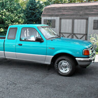
Got it, okay here is the harness they replaced; https://ford.oempartsonline.com/oem-parts/ford-wire-harness-kb3z15k867b
 

RangerLife

Member
First Name
Anthony
Joined
Jan 8, 2024
Threads
0
Messages
22
Reaction score
8
Location
USA
Vehicle(s)
2020 Ford Ranger
I am sorry I mistyped - 726-45-02 - It should be 0101-0100-0178, so its good

as far as 726-44-01 - 0101-0000-0175 - Leave it as is.
The problem with some (As-Built) Nomenclature - is its not always clear what it is:
ALM Conditioned Power Circuit Configure
I think is ref to (Always On Lighting Module) - I can only see that whatever it is when using the (As-Built) data compare between the trims (XL) has that set as (0)
Unsure at this point as to what it actually is (setting) I think its for diagnostic codes.

As far as both headlights (Driver's = Left) and (Passenger = Right) the damage to the driver's side may have shorted out the passenger side headlamp assembly
Left and Right is factored as you are sitting in the drivers seat.

As far as the harness - replacements - it depends on what specific harness they replaced, they should have listed a Part Number or Harness Number to identify the harness they replaced.
So if you can find that information - I can see what specific harness they replaced.
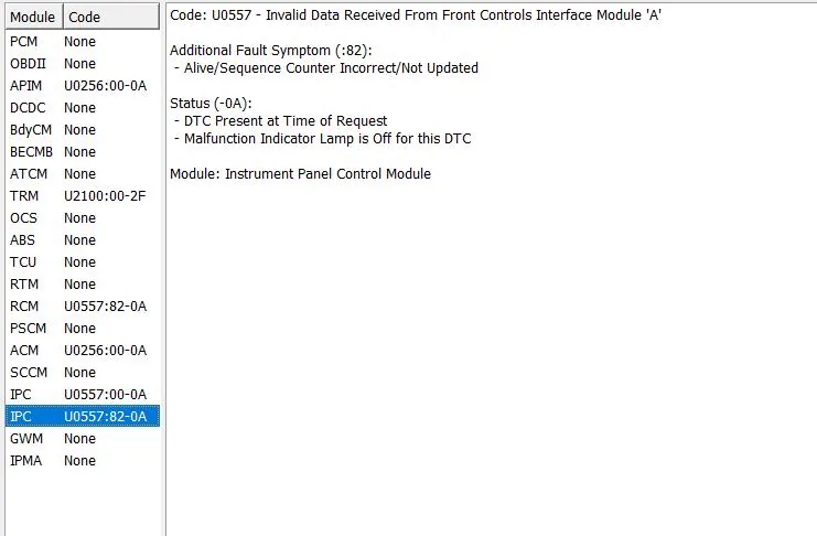
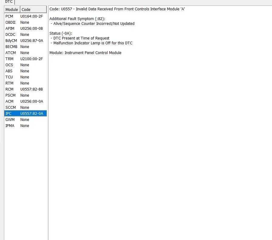
So something I found interesting, may be nothing, however I cleared codes, and ran for DTCs with both headlights unplugged and there were these DTCs:
1748299230776-k8.webp

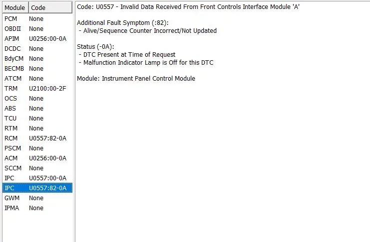
I then cleared the DTCs, plugged the headlights back in, and re-ran, and noticed there was a secondary IPC DTC, and the RCM DTC slightly changed as well:
1748299414774-ya.webp


1748299331433-rx.webp
 

airline tech

Well-Known Member
Joined
Aug 24, 2022
Threads
28
Messages
4,499
Reaction score
8,592
Location
Midwest - KS
Vehicle(s)
2022 Ranger Lariat-Super Crew, Cactus Gray
Occupation
Aircraft Tech
To breakdown all showing codes:

APIM (Sync)- U0256-00: Lost Communication with FCIM , sets when the APIM detects network messages are missing from the FCIM for more than 5-Seconds.

ACM (Audio Control Module) - U0256-00:
Lost Communication with FCIM , sets when the ACM detects network messages are missing from the FCIM for more than 5-Seconds when the ignition is (on)

RCM: (Restraint Control Module) - U0557-82 - Invalid data received from the FCIM, alive sequence counter incorrect/not updated - sets when the RCM does not receive an expected message from the FCIM.

IPC: U0557-82 Invalid Data Received from the FCIM, alive sequence counter incorrect/not updated - sets when the IPC receives invalid OAT (Outside Air Temp) data from the FCIM through the GWM

IPC: U0557-00 - Invalid Data Received from the FCIM
- sets when the IPC receives invalid OAT (Outside Air Temp) data from the FCIM through the GWM

TRM: Trailer Module - U2100-00 - Initial Configuration Not Complete
- sets due to incomplete or incorrect TRM Configuration
The TRM is set and configured by your previous posts, we can verify you are communicating to it because you can get into the (As-Built) information.
The fix for this code is to perform a PMI (Basically reload the data)
However with the FCIM having a (Communication) issue (MS-Can) this code is possibly related and ties into communication loss.

As I have stated, I think the issue is between the TRM and the FCIM, both of these modules are on the end of the communication line.
I know I had suggested - disconnecting the TRM and clearing the codes, to see if the FCIM came back online.
I do not recall if you had actually tried it.
My reasoning is the fact that although this is a Trailer Module, exterior lighting circuit ties into this module and with front end damage may have shorted this module out and this internal short is taking out the (Can Bus) circuit between the TRM and FCIM.

This is why it is VERY IMPORTANT to perform the Wiring Checks I have posted, you need to verify the wiring is good to the FCIM, mainly the Can Bus circuit.

Since some of these codes are specific to the (OAT)
Note:
Ambient Air Temp is Fed to the GWM (Gateway Module) via (HS Can 1) from the PCM (originating module) - Ambient Air Temp sensor direct feed to the PCM

The FCIM picks up that information from the GWM along the (MS-Can) bus and sends a data message that is has received the information (That is the data loss) that the IPC is reporting.

I do not know off hand if Forscan has this option or if you have tried it yet as I do not remember in the T-Shooting steps.

So, my thinking that this is not the issue for the complete FCIM not powering up, HVAC display greyed out (yes) possible- so if this has not been tried, attempt to reset and see if that helps the issue.

Plus, no other codes related to the (OAT) other than the FCIM (not sending) the data is another reason for me to think that the OAT sensor is not the root cause, although its still a possibility and this was one of the first things that I was looking at faulty.

To Confirm the the (Ambient Air Temperature) sensor is sending data to the PCM
Get into the (Live Data) PID's for the PCM and view - Ambient Air Temp it should match current air temp or close to it.
If the PCM is reading accurate data - then we can rule out the sensor if it is not then try the reset below.
If it still does not read correctly - then the sensor is bad or the wiring.
This is just a way to confirm if the sensor is bad, I do not think this is the issue, but it at least needs to be ruled out.


Reset the Outside Air Temperature Sensor Learned Values
Configuration
  1. NOTE: The ambient air temperature sensor is a critical component for correct Air Conditioning (A/C) and Heating, Ventilation, and Air Conditioning (HVAC) system operation. Make sure after the reset is carried out the temperature is displaying correctly in the vehicle.
    NOTE: The outside air temperature sensor is also referred to as the ambient air temperature sensor in this manual.
    Using the diagnostic FDRS scan tool, follow the on screen prompts to run and reset the outside air temperature sensor learned values.
 
Last edited:

airline tech

Well-Known Member
Joined
Aug 24, 2022
Threads
28
Messages
4,499
Reaction score
8,592
Location
Midwest - KS
Vehicle(s)
2022 Ranger Lariat-Super Crew, Cactus Gray
Occupation
Aircraft Tech
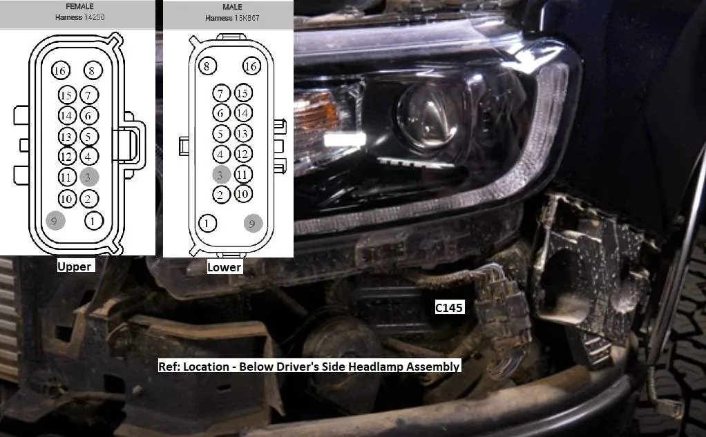
Ref: Harness replaced
This runs along the front bumper only and connects here

C145 Detailed.webp


This incorporates, Parking Sensor wiring (if equipped) Cruise Cont Module (if equipped)
Can Bus for the Cruise Cont Module and Power & Ground for each Fog Light, the harness also has the Grounds for the (Headlight Assemblies)

So possible tie in for the FCIM issue and that is the Cruise Cont Module powers via the DC/DC convertor and if that power feed is present in that harness it is possible that the DC/DC convertor received a shorted circuit at the time of the accident.

The Tie In - The DC/DC convertor feeds the BCM (Fuse 12) which is the FCIM, so (What IF?)
the DC/DC convertor has faulted that power feed out, I know you checked that fuse but did you verify actual battery voltage on it?
If you have voltage at the Fuse then you need to move over to the FCIM connector and verify power there as well.
Either way this MAY be the reason for the FCIM not powering, improper voltage coming in or the FCIM shorted out from the accident.

Also - with the FCIM swap over - The Hazard Switch changes from a separate switch (not part of the FCIM to integrated into the FCIM circuit board)
The hazard switch circuit is fed from the BCM, so just as a check, disconnect the other FCIM connector C2402B and then turn on the ignition and see if the FCIM Powers up, you will not have all Climate Controls but if the issue is within the Hazard Switch circuit then by disconnecting the connector C2402B (which is feeding the Hazard Switch) and other Climate Control related sensors - this can isolate it out of the (internal FCIM circuit)

This is just a thought of (What If?) and question is this a possible solution path is something within this circuit feed into the FCIM stopping it from powering up, note the power feed and MS-Can feed into the FCIM come from the other FCIM connector C2402A

My reasoning, in the accident the Turn Signal circuit was possibly shorted and also most likely you turned the hazards on - after the accident, this MAY have back fed into the FCIM.
 

airline tech

Well-Known Member
Joined
Aug 24, 2022
Threads
28
Messages
4,499
Reaction score
8,592
Location
Midwest - KS
Vehicle(s)
2022 Ranger Lariat-Super Crew, Cactus Gray
Occupation
Aircraft Tech
Ref: Data

TRM:

When the BCM receives a request for a turn signal, the BCM sends a turn indicator command message over the MS-CAN to the TRM to activate the requested stop/turn indicator output to the trailer tow connector.

When the parking lamps or headlamps position is selected, the BCM provides a ground path to the BJB parking lamps trailer tow relay (replaceable). When the BCM provides ground the parking lamps trailer tow relay, the relay is energized and the relay provides parking lamp voltage to the trailer tow connector.

So the above inputs to the TRM (Lighting Circuit) could have possibly had a short circuit, this short (if this is the case) can be the cause of the FCIM not getting the (ISP-R) data message, the TRM shorting out the MS-CAN bus

This is the reasoning for trying to disconnect the TRM and get it out of the circuit, again this is only a possible.

Your exterior lighting is working so power and grounds should be good for everything up front
But would be curious if the (Trailer Connector) is receiving output voltage from the TRM, mainly the Parking & Turn Signal.


Hazard Switch:

The BCM sends a voltage signal to the hazard flasher lamp switch to monitor for a hazard lamp function request. When the hazard flasher lamp switch is pressed, the voltage signal is routed to ground, indicating a request to activate or deactivate the hazard lamp function.

When the BCM receives a request for the hazard lamps, the BCM supplies on/off voltage to the front and rear turn lamps and sends a request to the door modules to flash the exterior mirror turn lamps.

So another avenue for a short circuit to reach the FCIM - Possible

When the wiring checks are done - post your findings and if needed dig deeper into the circuit.

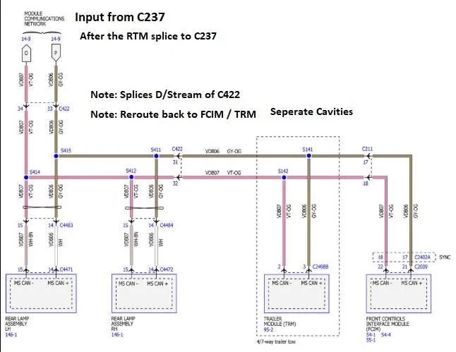
To repost the circuit in question.

It appears that even without BLIS the wiring is present in the Left Frame harness feeding C422 and then back feeds through the C422 connector over to the TRM.
You can Communicate to the TRM, however with the code you have tells me that there is still an issue with it or at least the full communication of it.

If you look at S141 & S142 (Splices) feed the C211 connector in the RH Kick Panel (which you pulled and reseated) - this connector feeds the FCIM (MS-CAN) wiring.

So a visual aid as to why I think the issue is between the TRM & FCIM as these 2 modules are on the end of the bus -if this proves to be bus related, either module or the wiring in between can cause the issue you have.
With disconnecting the TRM you will eliminate that module (IF -Internally shorted) as a possible source.

1748434557145-71.webp
Sponsored

 
Last edited:


Top